
Current Requirement
What this calculation gives you
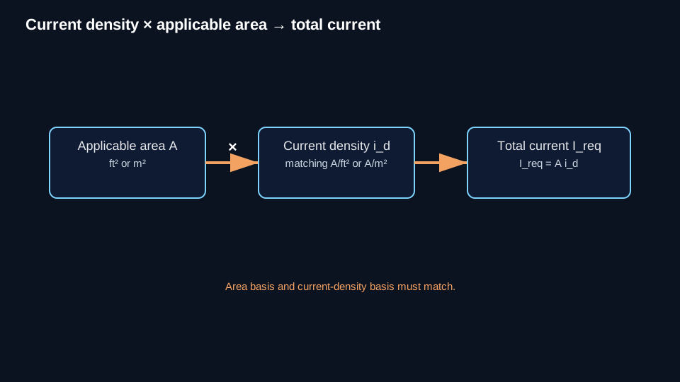
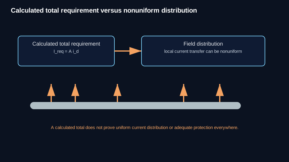
Estimate the total cathodic-protection current required for a defined structure and design condition when you have an applicable surface area and a source-controlled design current density. This answers how much current is required in total; it does not show where current will flow, whether it reaches every location uniformly, or whether every location satisfies a protection criterion.
Governing equation(s)
For an authorized area/current-density design basis:
Ireq = A × id
This relationship is conditional on the selected area and current-density basis; it is not an assumption-free universal current-requirement equation.
Variables
| Symbol | Meaning |
|---|---|
| Ireq | calculated design current requirement |
| A | surface area to which the selected current density applies |
| id | applicable, source-controlled design current density |
Units
Use compatible units so area cancels: ft² × mA/ft² = mA or m² × mA/m² = mA. Convert to amperes when needed using 1000 mA = 1 A.
Conditions and assumptions
- The selected current density is valid for the asset, environment, design condition, and area basis being used.
- Current density is not a universal CP constant.
- Area must correspond to the basis of the selected current-density model.
- No universal coating-efficiency or coating-breakdown factor is assumed.
- This calculation is a design estimate, not a field current-requirement test and not a measurement of actual CP system current.
Controlled example scope: NACE SP0193-2016 bare tank-bottom design range; Source-scoped design guidance only; do not generalize to pipelines, other tanks, coatings, structures, or environments.
Worked calculation
Given: applicable tank-bottom area = 1,000 ft²; selected design current density = 1 mA/ft². The value is within the SP0193 bare tank-bottom range and is used only as an example within that source scope.
Substitute: Ireq = 1,000 ft² × 1 mA/ft² = 1,000 mA. The ft² units cancel.
1,000 mA ÷ 1,000 = 1.0 A
Result: Ireq = 1.0 A
Interpretation
The calculated design current requirement is 1.0 A for the stated area/current-density basis. It does not prove that 1.0 A will distribute uniformly or that every location will meet a protection criterion. Actual rectifier/system current and measured shunt current are separate quantities.
Limitations
A field current-requirement test is a different route to the design question and remains tied to its test configuration and assumptions. Current Distribution & Attenuation owns the downstream question of whether current reaches different locations adequately; that subject is not public in this batch.
Common mistakes
- Treating current density as a universal constant.
- Multiplying a bare-area current density by total coated geometric area without authority.
- Applying a generic coating-efficiency or coating-breakdown factor.
- Mixing mA and A.
- Treating rectifier or shunt current as automatically equal to calculated current requirement.
- Treating current density and total current as interchangeable.
- Treating total required current as proof of adequate current distribution.
Technical visuals
Next action
Use the calculated requirement as a controlled input to system sizing. Use Current Distribution & Attenuation when the question is whether current reaches different locations adequately. Use the field current-requirement Method when a temporary-current test is the appropriate basis; that Method remains conditional and is not published here.