Pipe-to-Soil Potential Field Simulator — Coating Holiday (CP Applied)
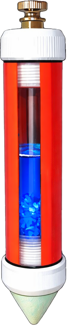
Drag the reference electrode from the meter and place it on the soil surface. Once the electrode is in contact with the soil, move it left or right across the ground to observe how the measured pipe-to-soil potential changes with position.
This simulation represents a pipeline that is protected by an active cathodic protection (CP) system. The voltmeter measures the electrical potential difference between two points: the pipeline and the surrounding soil electrolyte at the location of the reference electrode. This measurement is called a pipe-to-soil potential.
For the measurement to be valid, the porous tip of the reference electrode must make contact with the soil electrolyte. If the electrode is not touching the soil, the meter cannot measure the electrochemical potential of the electrolyte and the reading is meaningless. In this simulation, the meter displays PLACE CELL until the reference electrode is placed on the soil surface.
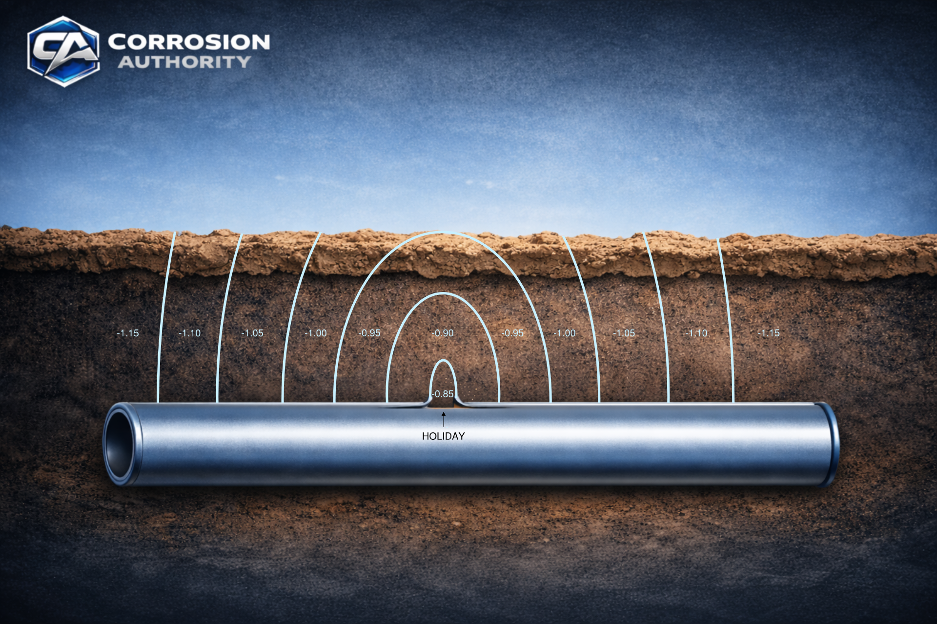
The curved lines shown in the soil represent equipotential contours surrounding a coating defect (holiday) on the pipeline. Because cathodic protection is applied, protective current flows through the soil and enters the pipeline at exposed metal surfaces. At the coating holiday, the pipeline surface behaves as a cathode, where reduction reactions occur and current enters the metal.
As protective current travels through the soil toward the pipeline, the electrical resistance of the soil causes a voltage gradient to develop in the electrolyte. This means the soil potential changes with distance from where current enters the pipe, creating regions in the soil that have slightly different electrical potentials. These regions are illustrated by the equipotential contours in the diagram.
Near the coating holiday, the exposed metal area is small, so the protective current becomes concentrated as it enters the pipe. This high current density near the defect produces steeper potential gradients in the surrounding soil. As a result, equipotential regions such as -0.850 V through −1.000 V occur very close to the pipe surface where the current enters the metal.
These regions occur below the soil surface, where the current density is highest near the exposed metal. Because the reference electrode in this simulation is positioned on the soil surface, it cannot directly measure these deeper potentials. Instead, it measures the soil potential at the surface directly beneath the electrode tip.
When the reference electrode is moved across the soil surface, it samples the soil potential at different locations within this potential field. The voltmeter compares the electrical potential of the pipeline with the local soil potential at the electrode tip. Even if the pipe potential remains essentially the same, the measured pipe-to-soil potential changes as the reference electrode moves through areas of different soil potential.
This principle is used in cathodic protection surveys. By moving the reference electrode across the surface and observing how pipe-to-soil potentials change, technicians can evaluate the distribution of protective current and identify areas where coating damage or current concentration may exist.