
Complete CP Circuit — ICCP System (Diagram #001)
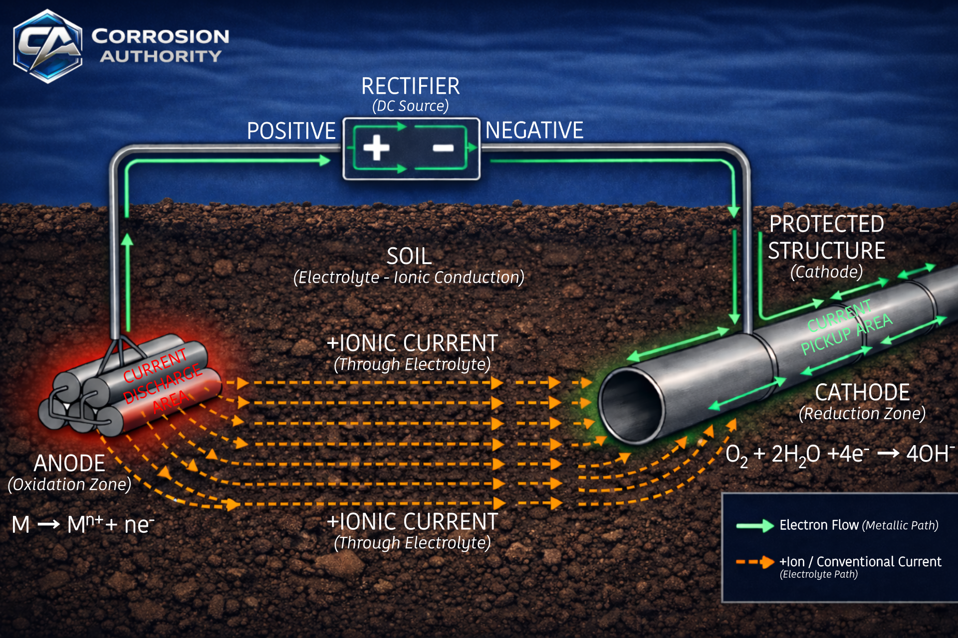
A complete impressed current CP circuit showing electron flow in metal, ionic current in soil, anode discharge, and cathodic protection current pickup on the structure.
What this visual explains
This diagram shows the complete impressed current cathodic protection (ICCP) circuit and how current must form a closed loop: electrons move through the metallic path while ions carry current through the electrolyte. It also anchors where oxidation and reduction occur so “anode vs cathode” stays consistent in field interpretation.
Diagram
How to read it
- Rectifier polarity: (+) feeds the anodes, (–) connects to the structure.
- Electrons (metal): travel through the metallic circuit (cables + structure).
- Ions (electrolyte): carry current through soil/water between anode and structure.
- Reaction zones: oxidation at the anode; reduction on the protected structure surface.
Field interpretation
- If any part of the loop is open (broken lead, poor continuity, dry electrolyte path), protection cannot be sustained.
- Use this mental map when diagnosing “rectifier looks normal but pipe readings don’t improve.”
- Always separate metallic conduction (electrons) from electrolyte conduction (ions).
Common mistakes
- Confusing electron direction with conventional current and flipping interpretations.
- Assuming current “travels in soil” without acknowledging it is ionic conduction.
- Labeling anode beds as “+ sources” instead of recognizing the rectifier provides the driving voltage.
CP 3 relevance
CP 3 troubleshooting assumes you can trace current paths quickly (metallic continuity, electrolyte paths, and reaction sites). This diagram is the baseline model for attenuation, interference, and “what the meter is actually seeing.”