
Surface Reaction Zones — Anodic vs Cathodic Sites (Diagram #002)
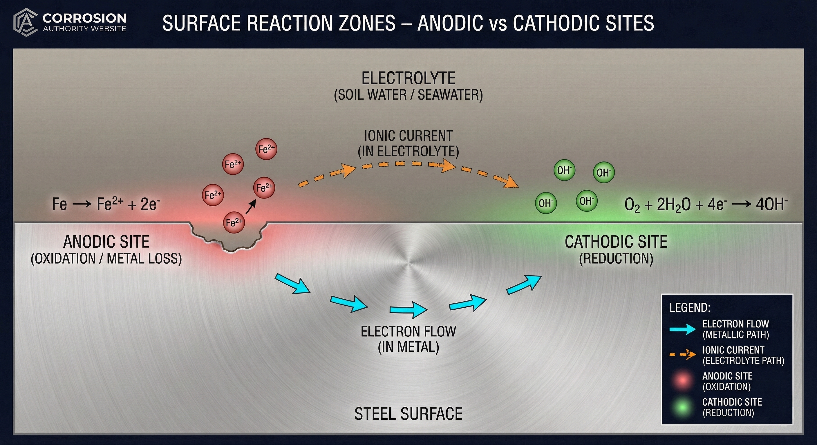
A steel surface with anodic (metal loss) and cathodic (reduction) reaction sites, showing electron flow in metal and ionic movement in the electrolyte.
What this visual explains
This diagram separates anodic and cathodic surface reaction zones. Corrosion is not “one reaction” — it is a coupled process: oxidation occurs at anodic sites and reduction occurs at cathodic sites, connected by electron flow through the metal and ionic current through the electrolyte.
Diagram
How to read it
- Anodic site: oxidation + metal loss (electrons produced).
- Cathodic site: reduction (electrons consumed).
- Metal path: electrons flow from anode sites to cathode sites.
- Electrolyte path: ions move to maintain charge balance in solution.
Field interpretation
- Corrosion occurs where current leaves metal into the electrolyte (anodic behavior).
- CP works by driving the structure surface to behave predominantly cathodically, suppressing anodic metal loss on the steel.
- Localized corrosion often reflects localized anodic areas (coating damage, shielding, disbondment, crevices).
Common mistakes
- Calling a physical object “anode” or “cathode” without referencing the actual reaction occurring at the surface.
- Forgetting the cathodic reaction must have access to reactants (oxygen/water/hydrogen evolution conditions).
- Ignoring the need for a complete circuit (metal + electrolyte) when explaining corrosion cells.
CP 3 relevance
Many CP 3 scenarios reduce to identifying where discharge is happening and why (shielding, interference, coating failure). This visual anchors the reaction logic used in interference and survey interpretation.