Reference-Electrode Placement
Quick answer
Reference-electrode placement changes what voltage gradients are included in a structure-to-electrolyte potential. Moving the electrode can therefore change the reading even when nothing about the structure itself has changed.
“Put the electrode over the pipe” is not a complete placement rule.
Where should the reference electrode go?
Place it where the measurement represents the intended structure/electrolyte condition and where unnecessary voltage-drop contributions are controlled as far as the survey method allows.
The correct location depends on the measurement purpose, current paths, coating condition, electrolyte, nearby anodes/groundbeds, and the region of the structure being evaluated.
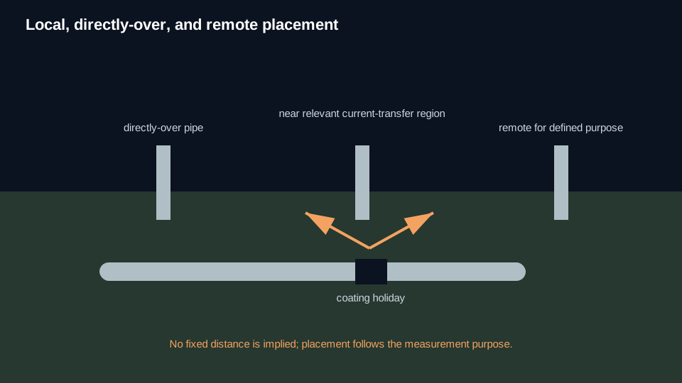
Close, directly over, and remote
Close / near means a location selected to shorten the relevant electrolyte path between the reference electrode and the structure/current-transfer region. There is no universal numeric distance that makes an electrode “close.”
Directly over describes surface geometry, especially on pipelines. It does not prove that the electrode is electrically close to the coating holiday or other location where current is actually entering or leaving the structure.
Remote means sufficiently outside the relevant current-transfer voltage gradient for a defined remote-earth purpose. “Remote” is functional, not simply “a long distance away.”
Why moving the electrode changes the reading
Current flowing through soil or another electrolyte creates voltage gradients. A structure-to-electrolyte measurement includes the voltage difference between the structure connection and the electrode location. Change the electrode location and the measurement can include a different part of that gradient.
This is why placement is part of interpretation, not just setup.
Coated structures
On a coated structure, the nearest surface point may not be the important current-transfer point. Current may enter through a coating holiday some distance away. Moving the reference electrode closer to the pipe surface can reduce some electrolyte-path voltage drop without eliminating the drop associated with a remote holiday.
Proximity can minimize a voltage-drop component. It does not guarantee a voltage-drop-free measurement.
Placement near anodes and groundbeds
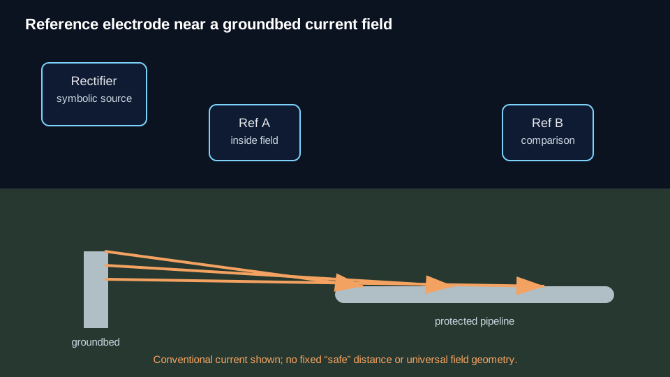
Anodes and impressed-current groundbeds create strong current fields. A reference electrode placed inside those gradients can include substantial electrolyte voltage drop in the measured potential.
A reading near a groundbed is not automatically wrong, but its spatial meaning must be understood. If the measurement purpose requires a structure potential representative of another location, relocate the electrode or use the appropriate survey/interpretation method.
Electrolyte contact
Placement also includes contact quality. Dry, frozen, rocky, paved, oily, or otherwise difficult surfaces can increase contact resistance and destabilize a reading. Poor contact can also make meter loading more important.
Do not solve a contact problem by treating it as IR drop. Check the electrode/contact condition and the measurement circuit separately.
Placement condition → likely effect
| Condition | Likely effect on interpretation | Next check |
|---|---|---|
| Electrode moved through a voltage gradient | Potential changes with location | Map the spatial trend; review IR Drop/current fields. |
| Electrode directly over coated pipe but holiday is remote | Surface location may not represent the current-transfer site | Review coating/current-path geometry. |
| Electrode near anode/groundbed | Reading may include strong electrolyte voltage gradient | Move/evaluate relative to current field. |
| Poor surface/electrolyte contact | Unstable or loading-sensitive reading | Check electrode contact and Meter Loading. |
| “Remote” point selected only by distance | May still be inside the relevant gradient | Establish remote condition functionally. |
What placement cannot fix
Changing electrode position does not automatically remove:
- metallic/longitudinal voltage drop;
- foreign or telluric current effects;
- meter loading;
- reference-electrode error;
- voltage drop associated with a remote current-transfer point.
What to check next
If placement is controlled but the reading still changes strongly between current-applied and interrupted states, review IR Drop and Current Interruption when their canonical resources are available.
If the reading changes when the meter or input resistance changes, review Meter Loading when its canonical resource is available.
If the question is what the potential itself represents, use Structure-to-Electrolyte Potential.
Technical visuals