
Stray DC Interference — Foreign Rectifier Effect (Diagram #008)
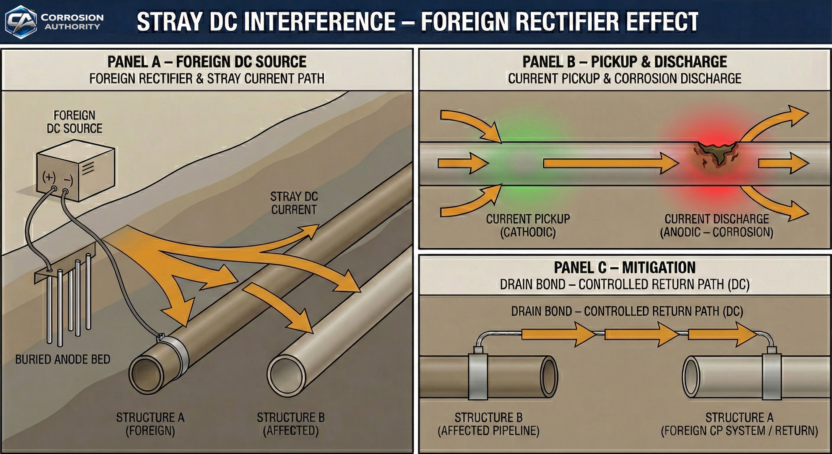
Shows how stray DC current is picked up by an affected structure and corrosion occurs where current leaves the structure; mitigation uses a drain bond return path.
What this visual explains
This diagram shows stray DC interference from a foreign rectifier system: an affected structure can pick up current in one area and discharge it elsewhere. Corrosion occurs where current leaves the affected structure (discharge).
Diagram
How to read it
- Foreign system: rectifier drives current from its anodes through soil to its protected structure.
- Pickup: affected structure intercepts part of the soil current.
- Discharge: current leaves the affected structure at another location (corrosion risk).
- Mitigation: drain bond provides a controlled return path to reduce discharge through soil.
Field interpretation
- Look for localized anodic areas on the affected structure where current discharges.
- Interference often varies with foreign rectifier output and operating state.
- Mitigation focuses on controlling the return path (bonding) and coordinating current sources.
Common mistakes
- Calling the pickup point “corrosion” (pickup is cathodic; discharge is anodic).
- Assuming you need a complete circuit shown at the pickup point to call it interference (the discharge completes it).
- Mixing up stray DC interference with structure-to-structure interference between two CP systems (#009).
CP 3 relevance
Stray current corrosion is a CP 3 core diagnostic topic. This visual supports identifying pickup vs discharge, interpreting potential changes, and explaining why drain bonds are used.