AC Interference
What AC interference means
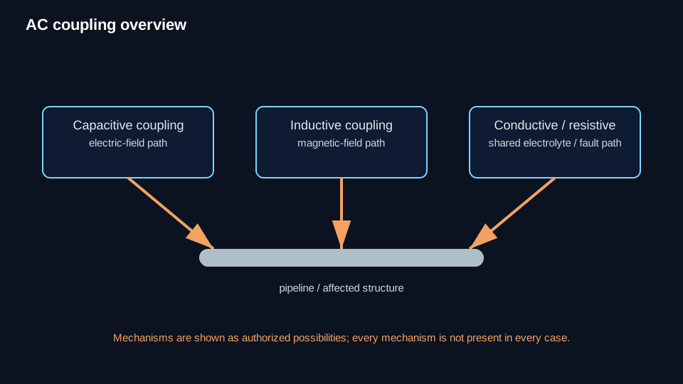
AC interference is the interaction of alternating-current electrical energy with a metallic structure. For buried pipelines and similar structures, exposure can arise through capacitive, inductive, or resistive/conductive coupling.
A measured AC voltage can show that AC exposure exists, but it does not by itself establish personnel safety, AC-corrosion control, localized current density, or the correct mitigation.
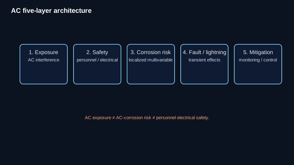
Keep five questions separate
- AC exposure/interference: how AC is coupled to the structure and how it varies with geometry and power-system operation.
- Personnel/electrical safety: whether accessible parts present shock hazards and whether fault/lightning conditions require protective design.
- AC-corrosion risk: localized, multivariable assessment using the applicable corrosion framework.
- Fault/lightning effects: abnormal electrical events that require their own safety/protective-design treatment.
- Mitigation/monitoring: whether control measures achieve the intended objective and remain effective over time.
How AC exposure occurs
Capacitive coupling transfers electric-field influence between conductors separated by an insulating medium. Inductive coupling results from the magnetic field associated with AC current in a nearby power system. Resistive/conductive coupling occurs through earth or another conductive path, including fault and ground-potential-rise conditions.
These mechanisms can coexist. AC induction is therefore not a synonym for all AC interference.
Safety is not the corrosion criterion
Within the supplied SP0177 treatment, a steady-state shock hazard is considered to exist at an accessible part when open-circuit AC voltage is 15 V rms or more. Capacitive-source capacity and fault touch/step voltage are separate safety questions.
The 15 V rms boundary is not an AC-corrosion criterion. A corrosion-risk result cannot be used as personnel-safety clearance, and a personnel-safety threshold cannot be used as the AC-corrosion criterion. Fault touch/step evaluation requires the applicable electrical-safety methodology.
AC-corrosion assessment is localized and multivariable
AC voltage is an exposure/driving variable, not a complete corrosion-risk metric. The controlled framework considers localized AC and DC current density, CP condition, local resistance/resistivity context, coating defects or coupons/probes, corrosion evidence, DC interference, and representative time exposure.
Conventional DC CP compliance does not by itself demonstrate acceptable AC-corrosion control. Soil resistivity is a risk-related input, not a standalone pass/fail criterion.
AC and DC current density
Current density is current divided by the area through which that current is evaluated: J = I / A.
Keep AC current density (JAC) separate from DC current density (JDC). State the current identity and units, coupon/defect area and units, conversions, and averaging/time basis. Current density is not total current.
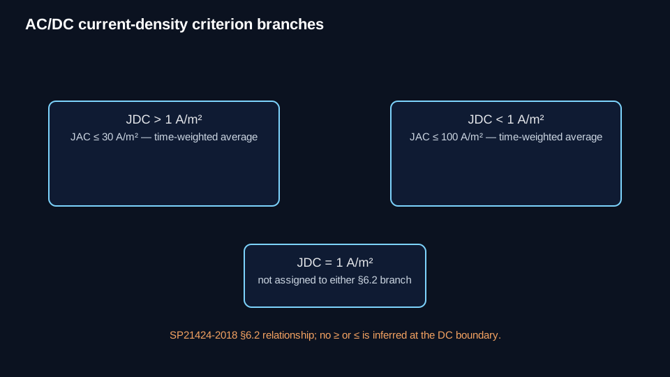
For the SP21424-2018 §6.2 current-density route, the controlled branches are JAC ≤ 30 A/m² when JDC > 1 A/m² and JAC ≤ 100 A/m² when JDC < 1 A/m², using the standard's stated time-weighted-average basis.
Boundary note: the supplied §6.2 wording does not expressly assign JDC = 1 A/m² to either branch. Corrosion Authority does not infer an equality rule.
Separate corrosion-rate route
SP21424 also provides a separate demonstration route based on a documented corrosion rate below 0.025 mm/y (1 mil/y) using suitable methods within the standard's stated context. This is distinct from the current-density route and from personnel-safety thresholds.
Coupons, probes, and time dependence
Coupons/probes provide a controlled local area for measurements relevant to AC-corrosion assessment. The area basis, soil contact/location, connection state, time basis, and representativeness limitations must be explicit. A coupon result does not automatically reproduce the maximum condition at every real coating holiday.
AC interference is dynamic. Use representative-period or datalogged evidence when the controlling assessment requires it; one spot reading must not be presented as representative of a time-varying condition.
Mitigation and verification
Mitigation is objective-specific. Supported families include grounding/gradient control, decoupling, conductor/mitigation systems, and monitoring/verification within their authorized scopes. None is a universal recommendation. Decoupling provides an AC/fault-current path while retaining DC-isolation implications that must be verified.
After mitigation, repeat the measurements tied to the original objective and confirm both the intended effect and any CP/isolation consequences.
Normal CP attenuation is different
Normal CP current distribution and attenuation describe the protected system's distributed electrical behavior. They are not AC interference models. Unexpected spatial behavior may justify an interference assessment, but it does not prove interference by itself.
Technical visuals