DC Interference
What DC interference means
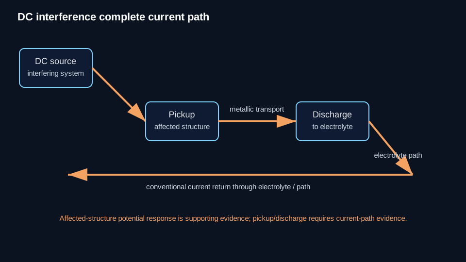
DC interference is an electrical disturbance in which direct current from a source external to the affected structure changes the structure's electrical condition. A foreign DC source can drive current through electrolyte into an affected metallic structure, through the metal, and back to electrolyte elsewhere.
Follow the current path
Use the physical sequence source → electrolyte/path → pickup → metallic transport → discharge → affected-structure response.
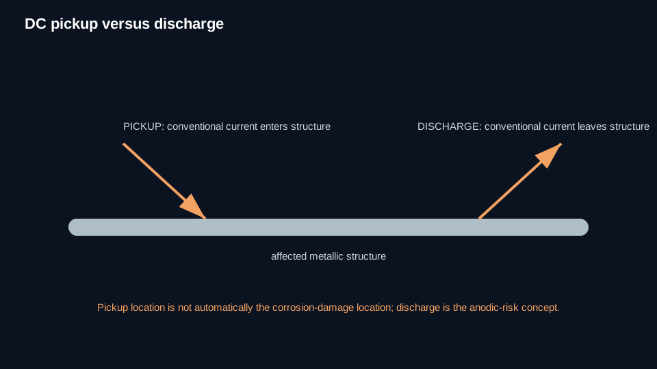
Current pickup is where conventional current enters the structure from electrolyte. Current discharge is where conventional current leaves the structure for electrolyte. For steel or iron, discharge is anodic and can accelerate metal loss. Pickup is cathodic influence and is not by itself evidence of corrosion damage at that pickup location.
Affected and interfering systems
The interfering structure/system is associated with the source or current path creating the disturbance. The affected structure is the structure whose electrical condition is changed. These labels describe the investigated relationship, not a permanent property of an asset.
Potential shifts are evidence, not proof
A more-negative potential shift during operation of a controlled source can be consistent with pickup/cathodic influence. A less-negative or more-positive shift can be consistent with discharge/anodic influence.
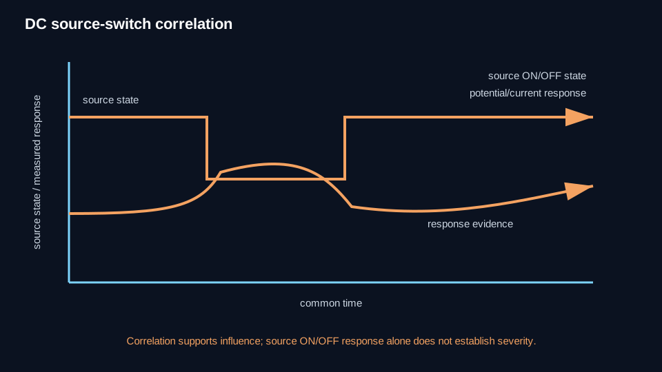
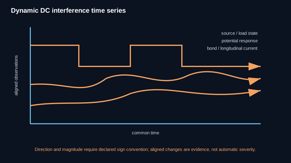
Potential response alone does not prove current direction, discharge magnitude, or corrosion severity. Interpretation must consider IR drop, reference-electrode location, polarization, bonds, other sources, current/gradient evidence, and measurement geometry.
Static and dynamic behavior
Static interference is comparatively consistent in magnitude, direction, and location. Dynamic interference varies and may reverse. Dynamic cases require synchronized or time-correlated evidence of adequate duration; a spot reading can miss the controlling condition.
Severity has no universal DC-interference number
No universal numerical DC-interference threshold is authorized by the controlling authority. Severity is evaluated using factors such as separation/routing, current magnitude, duration, current density, electrolyte resistivity, electrical discontinuities, applicable asset-specific CP criteria, and evidence of the current path and discharge.
Do not convert one mV shift, bond-current value, or generic current density into a universal pass/fail rule.
Bond and shunt direction control
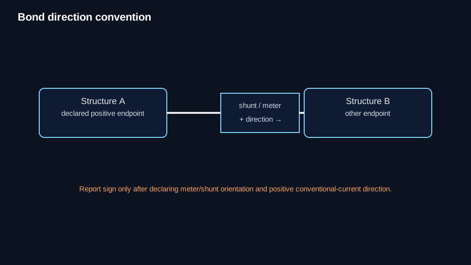
Current magnitude alone does not establish physical current direction. For bond or shunt measurements, declare meter/shunt polarity and the positive-current direction before interpreting pickup, discharge, or current transfer.
Mitigation changes the network
Supported mitigation families include galvanic discharge anodes, direct/resistance bonds, source reduction/removal/relocation, selected coating changes, shielding, isolation, and specialized directional/forced-drainage arrangements where applicable. A bond is not a universal remedy.
Any mitigation can redistribute current and change CP levels elsewhere. Post-mitigation testing must verify the intended reduction/control and check consequences on affected, interfering, and other relevant nearby systems.
Normal CP attenuation is different
Normal CP current distribution and attenuation describe the protected system's own distributed electrical behavior. Externally forced DC interference is a separate phenomenon. An unexpected attenuation profile can justify investigation, but it does not automatically prove DC interference.
Technical visuals