Structure-to-Electrolyte Potential
Quick answer
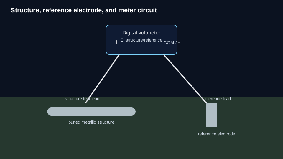
A structure-to-electrolyte potential is the measured voltage difference between a metallic structure and a reference electrode in contact with the associated electrolyte.
The displayed number is not self-interpreting. To use it correctly, know the reference electrode, polarity/sign, measurement state, electrode location, and whether voltage-drop or meter/circuit effects are significant.
Pipe-to-soil potential is the common pipeline-specific name for this same measurement concept.
Basic measurement circuit
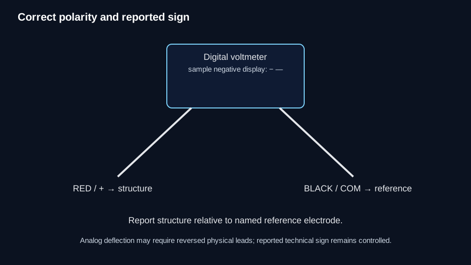
For the modern digital-meter convention used by the governing sources:
- connect the positive meter terminal to the structure;
- connect the negative/common terminal to the reference electrode;
- report the structure potential relative to the named reference electrode.
With a typical cathodically protected steel structure, the displayed value is commonly negative using this convention.
Some analog instruments require reversed physical leads to obtain upscale deflection. That instrument behavior does not reverse the technical sign of the structure potential being reported.
A potential value needs a reference
Do not report or interpret −850 mV as a complete technical value without a reference basis.
A controlled potential record should preserve at least:
- value;
- sign;
- units;
- reference-electrode type/basis.
For interpretation, also preserve as applicable:
- current state;
- reference-electrode placement/location;
- timing relative to interruption;
- asset/survey context;
- unusual interference/current conditions;
- meter/circuit validity where high resistance is possible.
Measurement state matters
| Measurement state | What the reading can represent | Main caution |
|---|---|---|
| Current-applied / ON | Structure-to-electrolyte potential while CP/influencing current is flowing | May include voltage drops outside the structure/electrolyte interface. |
| Instant-OFF | Immediate post-interruption measurement intended to approximate polarized potential | Validity depends on interruption, residual current, synchronization, transient rejection, and timing. |
| General OFF | A reading with some source(s) off | Do not assume it is Instant-OFF. |
| Native/open-circuit/free-corrosion | Potential without applied CP current under the defined condition | Ensure the system has actually reached the intended state. |
| Depolarization/decay reading | Potential during loss of polarization after current removal | Timing and criterion method matter; use the Polarization/criterion resources. |
What can be inside the displayed number?
Depending on the field condition, the reading can be influenced by:
- the actual structure/electrolyte interface potential;
- electrolyte voltage gradients;
- metallic/longitudinal voltage drop;
- reference-electrode condition and placement;
- meter loading;
- switching/transient effects;
- foreign, stray, long-line, or telluric currents;
- mixed-potential effects from electrically connected structures/environments.
The correct response is not to apply one universal correction. Identify which mechanism is plausible and use the corresponding technical resource.
Measurement is not criterion
A potential measurement is a measured electrical quantity. A CP criterion is a controlled interpretation rule that may specify asset type, reference electrode, polarization condition, and voltage-drop treatment.
Do not treat every structure-to-electrolyte potential as an automatic pass/fail criterion measurement. Criterion decisions belong in the applicable Criteria resource.
Common problems
The sign looks wrong
Confirm the meter connections, recorded sign, structure lead, and reference lead. Also consider whether an analog instrument required reversed physical leads for deflection.
The reading changes when the reference electrode moves
Review Reference-Electrode Placement. A spatial voltage gradient may be changing what is included in the measurement.
The reading changes when the meter changes
Meter loading may be involved. High circuit resistance relative to meter input resistance can alter the displayed value.
ON and OFF differ substantially
IR Drop, Current Interruption, and Instant-OFF Potential govern that interpretation. The difference can be useful, but it is not automatically equal to every unwanted voltage-drop component.
Two technicians get different values
Compare reference-electrode type/condition, placement, polarity, timing, meter input characteristics, contact quality, and current state before assuming the structure changed.
What to check next
Use Reference Electrode for electrode identity/condition and Reference-Electrode Placement for spatial meaning. IR Drop, Meter Loading, Current Interruption, Instant-OFF Potential, Criteria, and Reference-Electrode Conversion remain controlled neighboring subjects and should be used when their canonical resources are available.
Technical visuals