IR Drop in Cathodic Protection Measurements
Quick answer
IR drop is voltage drop produced when current flows through a resistive path. In cathodic-protection measurements, resistive voltage drops can be included in the measured structure-to-electrolyte potential and can change how the reading must be interpreted.
Always identify which current and which resistive path are involved.
The basic relationship
For a defined resistive path, V = IR.
That basic relationship does not mean every measurement error is IR drop. The path and current source matter.
Electrolyte IR drop
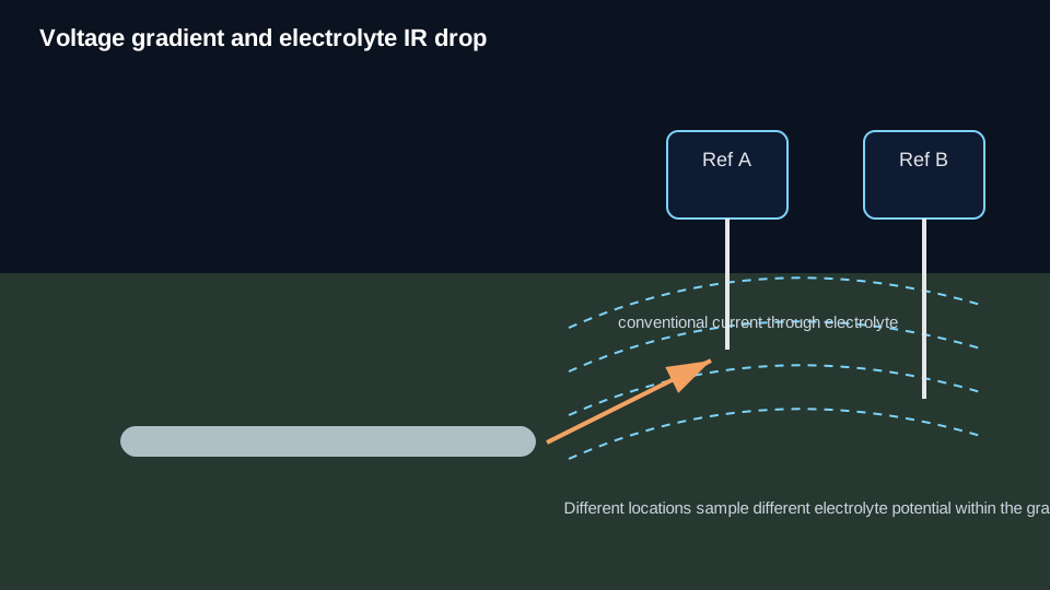
Current flowing through soil, water, or another electrolyte creates a voltage gradient. If the reference electrode and relevant structure/current-transfer location are separated within that gradient, part of the measured voltage can be electrolyte IR drop.
Reference-electrode placement can reduce the electrolyte path included in the measurement, but it does not guarantee that all relevant electrolyte voltage drop is removed.
Metallic or longitudinal voltage drop
Current can also flow through the resistance of the structure, test lead, bond, or other metallic path. A voltage difference can then exist between the structure connection point and the region represented by the reference-electrode location.
Keep this separate from electrolyte IR drop. Both are resistive voltage drops, but they occur in different paths and require different interpretation.
What is not the canonical IR-drop problem?
Contact resistance: Poor electrode/electrolyte or clip/lead contact can cause unstable readings and can increase meter-loading error. It is not automatically electrolyte IR drop.
Meter loading: Finite meter input resistance can alter the measured voltage when circuit resistance is high. That is a voltage-divider/loading mechanism.
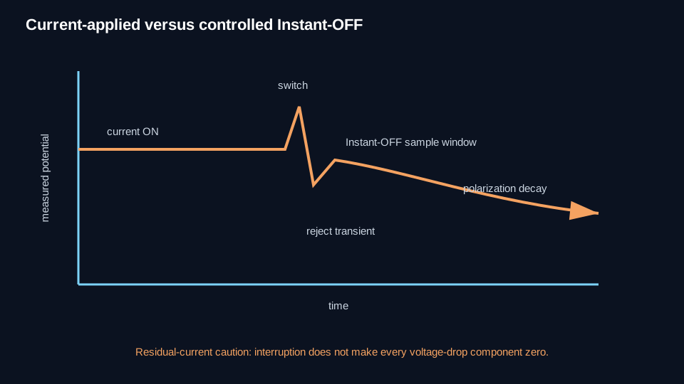
Switching/transient effects: Interruption spikes, meter response, sampling timing, and polarization decay can corrupt an Instant-OFF measurement. Do not label every dynamic error IR drop.
What placement changes
Moving the reference electrode changes the electrolyte path and voltage gradient included in the measurement. Close placement can reduce a corresponding electrolyte voltage-drop component.
It may not remove voltage drop to a remote coating holiday, metallic/longitudinal voltage drop, foreign/stray/long-line current gradients, meter loading, or reference-electrode error.
What current interruption changes
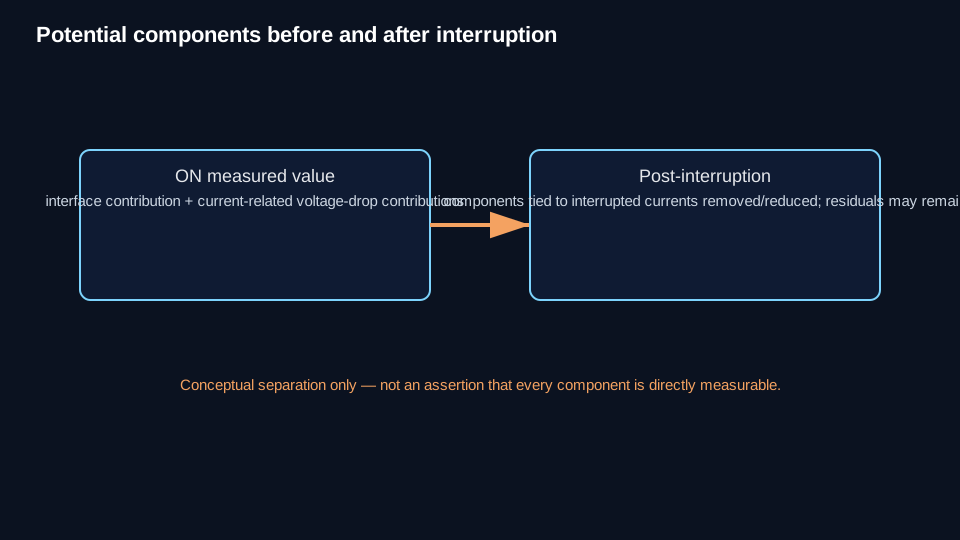
When a current is interrupted, the resistive voltage drop caused by that interrupted current can fall rapidly. This is why current interruption is useful for voltage-drop evaluation.
The field condition may still contain non-interrupted CP sources, galvanic current, foreign or stray current, long-line/telluric current, residual current paths, and switching/transient effects.
Instant-OFF is a technique for reducing or removing voltage-drop components associated with currents that were actually interrupted. It is not proof that all IR drop is zero.
ON minus Instant-OFF
The ON-to-Instant-OFF change can indicate the voltage change caused by interruption under controlled conditions.
Do not automatically call that difference “the IR drop” everywhere. Residual currents, incomplete interruption, placement, metallic gradients, transient effects, and timing can prevent the difference from representing every unwanted voltage contribution.
IR-drop source → consequence
| Source/path | Possible consequence | Best next resource |
|---|---|---|
| CP current through electrolyte | Potential includes spatial voltage gradient | Reference-Electrode Placement / Current Interruption |
| Current through structure/metallic path | Connection point differs electrically from represented region | Structure-to-Electrolyte Potential / survey-specific method |
| Foreign/stray current through electrolyte | Time/location-dependent voltage gradient | Interference / troubleshooting |
| High contact resistance | Unstable/loading-sensitive reading | Reference Electrode / Meter Loading |
| Finite meter input resistance | Displayed voltage depressed by loading | Meter Loading |
| Switching transient | False “instant” sample | Current Interruption / Instant-OFF |
Avoid these shortcuts
- “All ON readings are invalid.”
- “OFF removes all IR drop.”
- “Meter loading is IR drop.”
- “A fixed IR-drop correction works at every location.”
- “Putting the electrode over the pipe removes IR drop.”
What to check next
If the issue is where the voltage gradient is being sampled, go to Reference-Electrode Placement.
If the issue is the immediate post-interruption measurement state, go to Instant-OFF Potential. Current Interruption remains a controlled neighboring subject and should be used when its canonical resource is available.
If the reading changes with meter characteristics, use Meter Loading when that canonical resource is available.
Technical visuals